Focus on manufacturing various types of brakes
Having been deeply involved in the industry for thirty years, we provide you with various types of brake and friction plate products
SERVICEFocus on manufacturing various types of brakes
Having been deeply involved in the industry for thirty years, we provide you with various types of brake and friction plate products
SERVICEFocus on manufacturing various types of brakes
Having been deeply involved in the industry for thirty years, we provide you with various types of brake and friction plate products
SERVICEFocus on manufacturing various types of brakes
Having been deeply involved in the industry for thirty years, we provide you with various types of brake and friction plate products
SERVICEFocus on manufacturing various types of brakes
Having been deeply involved in the industry for thirty years, we provide you with various types of brake and friction plate products
SERVICE
Hydraulic brake not working properly? Why is this
Hydraulic brake is also a type of brake that can convert pedal force into hydraulic energy to transmit braking force. Its transmission structure is simple, but the braking torque it produces is linearly related to the pedal force. If the adhesion between the tire and the road surface is met, the braking force experienced by the car is linearly related to the pedal force. This function is called brake pedal sensation (commonly known as foot sensation), which allows the driver to directly feel whether the various working conditions of the car's braking equipment are normal, in order to quickly diagnose. Common faults in hydraulic braking systems include: ineffective braking such as brake biting. 1、 Brake failure 1. Appearance: When the car is moving, quickly press the pedal to the bottom, and the car cannot slow down or park immediately. Its braking The deceleration is small and the braking interval is too long. 2. Reason: (1) The pedal has excessive free travel. (2) Lack of brake fluid in the brake master cylinder, or blockage of the compensating hole, aging, swelling, deformation or overturning of the master cylinder leather bowl and leather ring. (3) The brake master cylinder piston and cylinder body are excessively worn and loose, causing oil leakage, poor sealing of the return valve, and broken tension spring of the outlet valve. (4) The brake cylinder cup is aging, swollen, and the piston is stuck. The cylinder piston and cylinder body are worn out excessively, resulting in looseness and oil leakage. (5) The brake shoes are severely worn, with excessive clearance or reversed clearance. (6) The brake drum is out of roundness, has grooves or is worn too thin, the brake shoe surface has oil, is burnt and hardened, and the rivets are exposed. (7) Air enters the hydraulic braking system, or the temperature of the braking system is too high, causing the brake fluid in the pipeline to vaporize and form air resistance. (8) The oil pipe is dented, the joint is loose and leaking, the brake hose is aged, broken or blocked.
07
2023-06
Working principle of explosion-proof electric hydraulic thruster
After the motor inside the hydraulic brake is powered on, it drives the centrifugal oil pump inside the hydraulic brake head, increasing the hydraulic oil pressure. Hydraulic oil transmits pressure to the piston in the oil cylinder, and the hydraulic push rod moves upward under the drive of the piston, opening the brake shoe. Technical data of hydraulic brake (taking MYTI-90 electric hydraulic thruster as an example): thrust of 900N, stroke of 80mm, rise time of 0.8S, fall time of 0.5S, power of 0.25kW, equipped with No. 20 engine oil, oil weight, 720 operations per hour, and matching brake model (thruster and brake combined to form hydraulic brake). Due to the frequent combination of thrusters and brakes, this article provides a comprehensive introduction to their installation, use, and maintenance points: 1) When installing and fixing the brake, attention should be paid to whether the brake shoes are parallel to the brake wheels when the brake is released, and in the braking state, the entire surface of the brake band should be attached to the brake wheels. The non parallelism and inclination within the brake wheel width of 100mm in the released state should not exceed 0.1mm. The working surface of the brake wheel should not have oil stains. 2) The brake is installed on the machine after the brake wheel is installed. The brake wheel is dynamically and statically balanced, and its surface roughness should not be lower than Ra1.6 and hardness should not be lower than HBS=280. 3) Before testing, the explosion-proof electric hydraulic thruster should inject clean and free of any contaminants or mechanical impurities into the hydraulic oil cylinder. The type and quantity of oil used should meet the specified requirements. 4) After connecting the power supply of the motor, check whether the impeller rotates flexibly, whether the cylindrical spring is stuck, and whether the push rod and piston move up and down normally. 5) Adjustment of the brake pad clearance of the brake. Due to the automatic clearance adjustment capability of the brake, the clearance between the left brake pad and the brake wheel remains constant as the brake band wears, but the clearance between the right brake pad and the brake wheel gradually increases with the wear of the brake band and needs to be adjusted as needed to maintain a uniform clearance between the two brake pads. The installation gap between brake pads and brake wheels is 0.6mm for brake wheels with a diameter of 150mm, 0.7mm for brake wheels with a diameter of 200-300mm, and 0.8mm for brake wheels with a diameter of 400-500mm. 6) Adjustment of braking torque. By adjusting the adjusting nut of the main spring and changing the compression length of the main spring, the spring force and braking torque can be adjusted to enable the brake to operate with the smallest possible braking torque.
02
2023-06
Do you know the working principle of electric hydraulic thrusters?
Electric hydraulic thrusters are mainly used in mining and other places. Some workers working here are familiar with this. The propulsion of the machine relies entirely on its function. It can be said that without electric hydraulic thrusters, the machine cannot start normally. But do you know the working principle of electric hydraulic thrusters? How does it work in industry? Below, we have compiled some knowledge about electric hydraulic thrusters for everyone. First point: Working process of electric hydraulic thruster: After the motor in the hydraulic brake is powered, it drives the centrifugal oil pump in the hydraulic brake head, increasing the hydraulic oil pressure. Hydraulic oil transmits pressure to the piston in the oil cylinder, and the hydraulic push rod moves upward under the drive of the piston, opening the brake shoe. Point 2: Working principle of electric hydraulic thruster: Technical data of hydraulic brake (taking the technical data of MYTI-90 electric hydraulic thruster as an example): thrust of 900N, stroke of 80mm, rise time of 0.8S, fall time of 0.5S, power of 0.25kW, equipped with No. 20 engine oil, oil weight, and operated 720 times per hour. After reading these, I believe you have gained some understanding of electric hydraulic thrusters. I hope everyone can take more care of them when using them, so as to ensure steady operation.
02
2023-06
3 easy ways to maintain electric hydraulic brakes
Electric hydraulic brakes are different from electric hydraulic brakes. They are mainly used to help machines start a propulsion device. Without them, the machine cannot operate normally, so this device is more commonly used in daily life. After using it too much, how to extend the lifespan of the machine has become a problem. People often say that machines require 70% maintenance and 30% repair. How to maintain this equipment? Next, let me explain it to you all. The first trick: Regularly replace vulnerable parts to prevent rubber parts from aging, usually within 1-2 years. Second move: The brake fluid of the electric hydraulic thruster in the reservoir should not be lower than the lower limit. When adding brake fluid, attention must be paid to cleanliness, and dust and dirt must not be mixed into the reservoir to avoid brake system blockage and brake failure. The third trick: During maintenance, it is necessary to check the tightening torque of fasteners at all times to prevent loosening In short, with proper maintenance, the lifespan of electric hydraulic thrusters is naturally extended. At the same time, when purchasing equipment, choose products from large manufacturers to avoid a series of problems in the later stage.
02
2023-06
INDUSTRY TRENDS
11-25
2024
Where are the friction plates used for wind turbine yaw brakes
The friction plates of wind turbine yaw brakes are mainly used in the yaw braking system of wind turbines. The following is a detailed answer about the application of friction plates in wind power yaw brakes: Application scenarios The friction plate of wind turbine yaw brake is mainly used in the yaw process of wind turbines, playing a role in braking and stabilizing the unit. When the wind turbine needs to adjust its direction to align with the main wind direction, the yaw brake will be activated. Through the friction between the friction plate and the brake disc, the necessary damping torque is generated to enable the unit to smoothly and accurately complete the yaw action. working principle In wind turbines, the yaw brake is usually driven by a hydraulic system. When braking is required, the hydraulic system provides pressure to clamp the brake caliper body against the friction plate, which then comes into close contact with the brake disc, generating friction torque. This friction torque will hinder the rotation of the unit, allowing it to maintain a stable position. At the same time, by adjusting the pressure of the hydraulic system, the magnitude of the friction torque can be controlled, thereby achieving precise control of the yaw speed and yaw position of the unit. Usage requirements Friction coefficient: The friction coefficient of the friction plate of the wind turbine yaw brake is a key parameter. A suitable friction coefficient can ensure that the brake can provide sufficient braking torque while avoiding excessive wear on the brake disc and friction pads during operation. 2 Wear resistance: Due to the frequent operation of yaw brakes in wind turbines, friction plates must have good wear resistance. This can extend the service life of the friction plate, reduce the frequency of replacement, and thus lower maintenance costs. Stability: During the braking process, the friction plate needs to maintain stable friction performance. This requires friction plate materials to have good thermal and chemical stability, and be able to work normally in harsh environments such as high temperature, high pressure, and humidity. 4 Adaptability: Different wind turbines may have different requirements for the size, shape, and material of the friction plates. Therefore, when selecting friction pads, it is necessary to ensure their adaptability to ensure that the brake can work properly and meet the braking requirements of the unit. Maintenance and replacement In order to ensure the normal operation of the friction plate of the wind turbine yaw brake, it is necessary to regularly inspect and maintain it. If severe wear or other faults are found in the friction plate, it needs to be replaced or repaired in a timely manner. When replacing the friction plate, it is necessary to ensure that the size, shape, and material of the new friction plate are consistent with the original friction plate, and strictly follow the manufacturer's installation guide for installation and adjustment. In summary, the friction plates of wind turbine yaw brakes play a crucial role in wind turbines. They ensure the efficiency and safety of wind power generation by providing necessary braking torque to ensure that the unit can smoothly and accurately complete the yaw action.
DETAILS+INDUSTRY TRENDS
11-21
2024
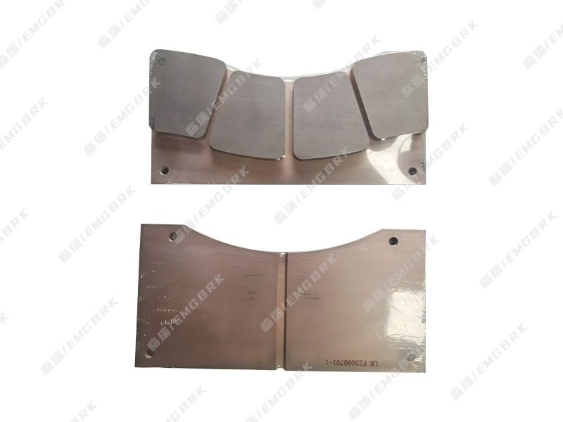
SHI252 hydraulic disc brake pads
The SHI252 hydraulic disc brake pad elevator, as the main tool for transporting materials in coal mines, undertakes the main task of coal mine transportation. Its normal operation is the prerequisite for ensuring safe production, and whether it can operate normally is the the final say of brake shoe clearance. Too large or too small brake shoe clearance will affect the brake system of the elevator, so the brake shoe clearance can determine whether the elevator can operate normally. However, in normal production, it is quite normal for the brake shoes of the hoist to wear out quickly. If you do not notice at this time, or if the wear rate of the brake shoes accelerates and you have not had time to replace them, it will inevitably affect the normal operation of the hoist, and the incidence of safety accidents will greatly increase. Therefore, in view of the rapid wear and tear of the hoist brake shoes, installing brake shoe protection is an effective means to avoid safety accidents. The reason why we are so confident in coming to this conclusion is because of the unique features of brake shoe protection: 1、 Gap detection of gates Detection principle: By using a displacement sensor, a distance of 0-10mm is converted into a voltage signal of 010V, which is transmitted to the analog input module of the PLC. Due to the impossibility of tightly adhering the end face of the sensor to the brake disc, a certain distance is set to the 0 position, such as setting 4mm as the 0 position. When in the closed state, adjust the displacement sensor so that the sensor end face is approximately 4mm away from the brake disc, and set it as 0. When the gate is opened, if the detected distance is 5. Imm, then the gate gap is 5.1mm-4.0mm=1.1mm. However, after long-term operation, there will be a certain amount of wear on the brake shoes. Assuming the wear value of the brake shoes is 1.2mm, at this time, when in the closed state, the distance detected by the sensor is Imm 1.2mm=2.8mm, while when the brake is opened, the distance detected by the sensor is 5.1mm+1.2mm=6.3mm. At this time, the gap between the brake shoes is 6.3mm-4.0mm=2.3mm. (It can be seen that both spring fatigue and brake shoe wear will increase the brake clearance). The above calculations are all completed in the PLC controller. In actual use, simply adjust the sensor to * * * 0 position in the closed state 2、 Brake shoe wear detection The detection principle of brake shoe wear: When the output oil pressure of the hydraulic station is detected as 0 or residual pressure, if the value of the distance sensor is less than 0 (negative), it is considered that the value is caused by brake shoe wear. The reverse of the change value is the wear amount of the brake shoe. (This value may also be caused by the bias of the brake disc, and the impact of the bias needs to be deducted in the specific fault diagnosis). 3、 Brake disc deflection detection Calculation of brake disc deflection: Fixed to the brake seat by a distance sensor, the winch detects the maximum and minimum values of the distance during operation, and the difference between the maximum and minimum values is the deflection. How about it? After reading the above content, you will understand why the editor confidently said that "installing brake shoe protection is an effective means to avoid safety accidents." It is recommended that coal mine operators always tighten the safety string, nip accidents in the bud, and start with installing brake shoe protection
DETAILS+INDUSTRY TRENDS
06-07
2023
Common faults and troubleshooting techniques of electromagnetic hydraulic thrusters
When using electromagnetic hydraulic thrusters, it is inevitable that some problems may occur. In response to this, how should we handle and eliminate their faults? Next, I will explain it to everyone, hoping it can be helpful to you. After connecting the electromagnet, the armature cannot be pulled up. It is necessary to check whether the mechanical part of the electromagnetic brake is intact. 2. Electromagnets make noise. AC electromagnets often produce noise due to complete attraction, uneven surface, or broken short-circuit rings. Such faults can be addressed by eliminating mechanical jamming, replacing the iron core or short-circuit ring, etc. 3. The temperature of the electromagnet coil is too high, which can be caused by incomplete attraction of the AC electromagnet, excessive current in the series coil, or too frequent power supply, all of which can cause the temperature of the electromagnetic brake electromagnet coil to be too high. 4. After the electromagnet is powered off, the armature does not fall, and the reasons for such faults are mostly due to brake mechanical jamming or frozen lubricating oil. The residual magnetism of the DC electromagnet is too large, and the non-magnetic gasket is worn. In summary, these are the common faults and troubleshooting techniques of electromagnetic hydraulic thrusters. I hope they can be helpful to you. That's all for this knowledge, and I hope it can be helpful to you.
DETAILS+INDUSTRY TRENDS
06-07
2023
What are the common problems with the brake system
Brakes are one of the most important components in car operation, and without them, we may not be able to complete parking. But many people who have driven cars will encounter situations where the car runs to one side when braking. Let's analyze it from the perspective of the brake. Possible reasons for this situation include: 1. The gap between the wheel brake drum and the friction plate is uneven, and the contact area between the two front wheel friction plates is too different. 2. The piston of one side of the wheel cylinder conflicts too much with the cylinder, there is air in one side of the front wheel cylinder, the hose is aging or the cylinder cup is poor, or the brake drum on one side of the front wheel is out of circle. 3. The degree of wear and tear on the tire brake shoe support pin sleeve varies. 4. Frame deformation, front axle displacement, inadequate toe in, loose steering organization, and uneven tension of the two front steel plate springs. The maintenance sequence after the problem occurs: first, brake through road test; Check if the brake pipeline of the wheel is leaking oil and if the tire pressure is sufficient; Gap between high-speed friction pad and brake drum; Check if the air enters the sorting pump; Remove the brake drum and inspect each component of the brake one by one according to the reason; The skill and steering organization of the frame or front axle should be checked. Do you now have a better understanding of this situation? The brake manufacturer reminds you that if there is a problem with the car, it must be repaired in a timely manner, and do not have a feeling of relief.
DETAILS+INDUSTRY TRENDS
06-02
2023
How to choose a suitable and desirable brake
There are different types of brakes, and under different usage requirements and working conditions, how can one choose a suitable and desirable brake? Next, let me explain it to you, hoping it can be helpful to you. 1. The working nature and conditions of the machine or mechanism that needs to be applied. For example, normally closed brakes are used for the lifting and slewing mechanisms of cranes. For vehicles and lifting machinery operating horizontally and rotating mechanisms, in order to control the magnitude of dynamic torque for accurate parking, normally open brakes are often used. 2. Full attention should be paid to the task of the brake. For example, there is sufficient margin for the braking torque of the object brake, which should ensure a certain safety factor. For mechanisms with high safety requirements, dual brakes need to be installed. For example, in a mine hoist, in addition to setting brakes on the high-speed shaft, brakes are also installed on the drum or rope shaft. For heavy object descent braking (i.e. sliding friction braking), heat dissipation should be considered, with sufficient heat dissipation area to dissipate the heat generated by the potential energy of the heavy object during braking, in order to prevent overheating and brake failure. 3. The application location should be considered. For example, if there is sufficient space at the location where the brake is installed, an external holding brake can be used. If the space is limited, an internal shoe, belt, or disc brake can be used. Overall, the selection of brake type is mainly related to the working conditions, and users need to choose according to the specific working environment.
DETAILS+INDUSTRY TRENDS
06-02
2023
Instructions for using hydraulic brakes
There are two types of brakes: hydraulic brakes and block brakes. When using different types of devices, we need to adopt corresponding methods and understand their precautions. Next, taking hydraulic brakes as an example, we will explain their usage. What should be noted during the use of hydraulic brakes? In order to ensure the uninterrupted operation of hydraulic brakes, it is necessary to regularly protect and safeguard them: 1. Lubricants are often added to the mobility of electromagnetic brakes. 2. Regularly check the length of the armature stroke. Because during the operation of the brake, the stroke length of the armature will be longer due to the wear of the cutting surface. When the stroke length of the armature does not reach the normal value, it is necessary to adjust it to compensate for the small gap between the moving surface and the turntable. If the stroke length of the armature exceeds the normal value, it may greatly reduce the suction force. 3. If the worn brake surface is replaced, the small gap between the brake surface and the turntable should be adjusted properly from the beginning. 4. Regularly check the tightness of bolts, especially tighten the bolts of the electromagnet, the bolts between the electromagnet and the housing, the bolts of the magnetic yoke, the bolts of the electromagnet coil, and the wiring bolts. 5. Regularly check the mechanical wear condition of movable components and remove dust, debris, and dirt from the surface of electromagnetic components.
DETAILS+0391-7543530